Structural Evaluation and Renovation
The following report summarizes the results of the structural evaluation of ---------------------. This structural evaluation and report have been prepared at the request of ------------------------- to check the condition of the buildings and their suitability to continue serving their original function. Evaluation work started in ---------------. The evaluation process considered visual inspection and tests conducted through the laboratory ----------.The following is a list of findings contained within this report and subsequently recommended reparation.
No structural defects or concrete deterioration were found in the main school building and other auxiliary buildings.
Most of the structural elements are overdesigned,
Laboratory test results were found to be satisfactory and reassuring.
All seen defects and deterioration are cosmetic that exist within the plaster layers or between two different materials; i.e. concrete element and block work.
The structure could be operational for approximately another 12 years or even more with periodical maintenance maintained.
Expansion joints filling material to be replaced.

1) Scope of Investigation
Several investigation visits were made, and a visual inspection of buildings was conducted. Photos of buildings and deteriorated areas were taken, as well as of the tested elements. Structures were investigated for any surface imperfections such as cracks, distortion, sagging, excessive deflections, significant misalignment, signs of leakage, and peeling of finishes.Based on the site observation, a spatial condition matrix was developed and a sufficient number of typical structure members were examined to draw reasonable conclusions and to evaluate the effect of time with respect to the deterioration of the original construction materials.
Review of all available drawings, reports, maintenance records, or any other pertinent documents.
Appropriate tests to evaluate the properties and condition of the concrete and reinforcement steel were conducted. The conducted tests are summarized in table 1.
Table 1, Conducted laboratory tests
SN. | Test | No. of Tests |
1 | Ultrasonic pulse velocity test ( to be on Original Concrete) | 28 |
2 | Drilling concrete cores (4' dia, 6' depth) | 20 |
3 | Compressive Strength of Concrete Cores | 20 |
4 | tensile test for collected steel samples | 3 |
5 | Concrete Carbonation | 20 |
Perform structural analysis for the significantly deteriorated condition or distress of important structure elements, if warranted, to determine if there are any safety issues.
2) Existing Construction and Documentation
2.1. General
The school premises consist of several buildings, figure 1. From previous experience and the records available, this type of school is one of those were in use since 1986, i.e. 30 years old. The main school building is of an approximate area of 3561m2, consisting of 2392m2 on the ground level and 1169m2 first floor. The courtyard area is covered with a space truss. The building contains classrooms, offices, labs, and a gymnasium.Buildings 1 and 2 are 139.88 m2 and 150.53 m2 respectively and contain classrooms.
Building 3 is the mess hall; the area of the building is 272.63 m2.
Building 4, approximately 277.62 m2 and contains the praying rooms.
CTV Control room, approximately 63.61m2.
In addition, the school premises contains a number of small buildings (less than 35m2) that are utilized for various services, e.g. ER, PR...etc.
2.2. Structural System
2.2.1. The main building is a concrete structure building made of 400mm thick conventional concrete slab floors supported by concrete beams which are in turn supported by concrete columns and concrete walls that transfer loads to the rock strata through isolated and strip footings. Classroom columns are of sizes 200/300mm x 700/800mm and are distributed regularly on 7.6m grids. The Multi-purpose hall roof slab is paneled beams slab in the short direction; the 13.6m direction. The concrete paneled slab is supported by concrete perimeter beams that in turn supported by concrete rectangular columns which transfer the load to the rock strata through isolated footings. From previous experience with such schools type, two types of footings are used, isolated footing of sizes 1.8x1.8x 0.5 m and 2x2x0.5m for round columns and inverted T section strip footings of 2m width and 0.5m depth under rectangular columns. Figure 2 shows the strip footing and the extracted core from it.Figure 2, Strip footing at main building edge columns and extracted core
2.2.2. Buildings 1 and 2 are one-level concrete buildings made of conventional two-way slabs supported by concrete perimeter beams that in turn supported by concrete rectangular columns which transfer the loads to the rock strata through isolated footings, figure 3.
2.2.3. Building 3; the mess hall. The building is a steel frame structure covered with a corrugated sheet roof and concrete blockwork walls, figure 4.
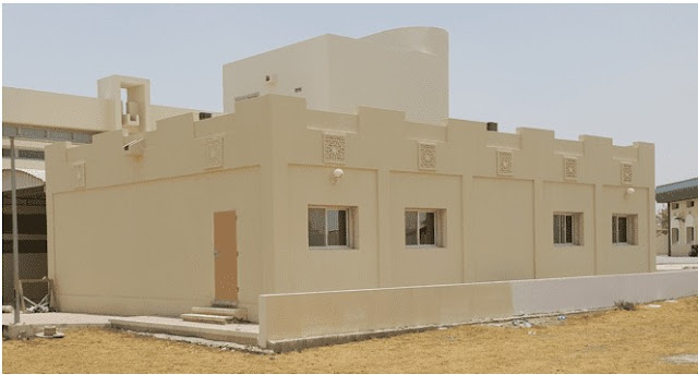
2.2.4. Building 4, the prayer rooms, is a concrete building made of a conventional two-way slab supported by concrete perimeter beams that in turn supported by concrete rectangular columns which transfer the loads to the rock strata through isolated footings, figure 5.
Figure 5: Praying rooms
2.3. Building function and acting loads
Buildings are to remain to function as they were originally built for; school. No changes in the applied Live load patterns will be experienced. Self-weight and finishes are similar to those considered for the original design since no alteration was done to the buildings.
2.4. Available Documents
Neither construction documents nor structural and architectural drawings were available for the buildings, only as-built architectural drawings provided by the contractor were available. Thus, evaluation analysis was based on physical measurements and in-field obtained information, observation, and test results.
3) Field Observations and Condition Survey
3.1. General
During the physical observation, considerable areas were exposed and checked, and a general assessment was conducted. Investigation for cracks’ patterns, signs of excessive deflection and distress, spalling of concrete, flexural and shear cracks was carried out.
3.2. Observations
In general and apart from a few cases that will be mentioned hereafter, all investigated areas were in good condition and no signs of deterioration or deformation were observed. Concrete cover was removed in the investigated areas and the concrete condition of these areas was found to be good. During core extracting steel condition was checked, and concrete tend steel corrosion was found and no concrete carbonation at all, see figure 6.In addition, it is worth mentioning that steel sizes found in columns were heavily reinforced and above the required for such types of structures and loads; ᶲ32mm in 400mm circular columns, ᶲ16mm in 250mm columns, and 200/300mmx700/800mm rectangular columns, figure 6.
Figure 6: Column’s core showing no carbonation and reinforcement size
It was noted that the filling material for expansion joints at the first-floor level has lost its physical properties and become obsolete, and they penetrate water whenever exists in the first-floor corridors.
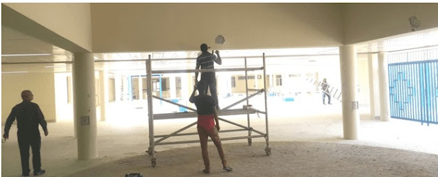
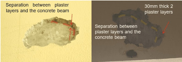
Some hair cracks (<0.3mm) were noticed in the corbels at the expansion joints, after investigation and chipping the finishing layer it was found that these cracks are just in the plaster and do not continue in the concrete corbels itself. Also, a drum sound was noticed (when hitting the concrete with a metal rod) in the parapet beams at the open area in the locations shown in figure 7. After removing the plaster layer and exposing the concrete element, it was clearly noticed that this sound occurs due to the separation between the thick implemented plaster layers and the concrete beam, and no spalling for beam cover exists, i.e. no cover separation due to steel corrosion.
Apparent separations were noticed between block work and concrete columns and beams in several locations. This type of separation is obvious when no plaster accessories are used at joints between block work and concrete due to the temperature variation throughout the long service period and the difference in thermal expansion coefficients between different materials, figure 9 shows examples of these separations.
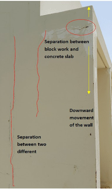
Visible separation was noticed in building 1 between the parapet slab and the block walls, figure 10. This separation occurred due to the thermal expansion difference between the concrete slab and the block wall and the volume change of the parapet slab that was exposed directly to solar radiation.
4) Sampling and Material Testing
4.1. General
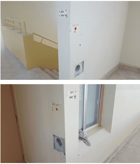
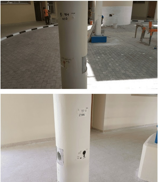
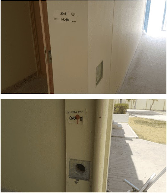
Considering the fact that the evaluation process engaged at the latest stage of buildings’ renovation, it was unfeasible to freely introduce damage to the structural elements by removing concrete covers and exposing steel, removing tiles and false ceilings, etc. hence the tests and samples extracting were based on the criticality of the element and where the sign of distress or excessive deterioration occur. Cores were extracted from columns and walls where compressive strength is the main strength factor. Although no sign of steel corrosion or excessive deformation in beams and slabs was noticed, steel samples were extracted from the roof’s beams and slab. Ultrasonic test at cores locations was done to produce a confident correlation between compressive strength and ultrasonic speed to assist in evaluating the compressive strength of columns where no cores were taken. Figures 11 and 12 show the locations of cores and ultrasonic tests.4.2. Tests Results
Annex A shows photos of cores and ultrasonic locations. The laboratory tests report is attached at the end of this report, Annex B. Table 2 summarizes the laboratory results received from ACES, report No. SPR16000081.Table 2: Summary of ACES laboratory results for concrete compressive strength
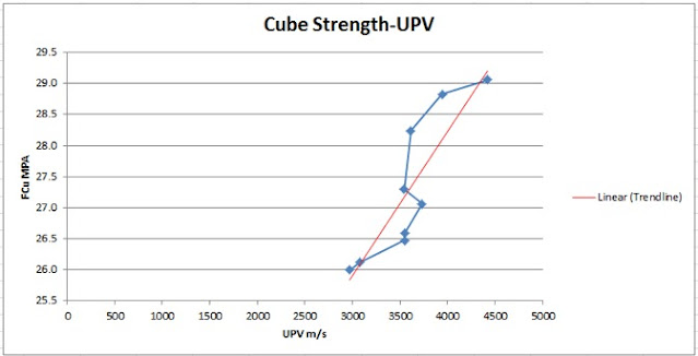
A correlation between the Ultrasonic test and compressive strength test was derived to provide a reliable concrete strength estimate for those columns not checked by extracted core compressive strength. The graph in figure 13 shows the Cube Compressive Strength – UPV relation.
Figure 13: Cube Compressive Strength – UPV relation
4.3. Results discussion
From the results obtained, one can deduce that the concrete strength obtained through Uniaxial Compressive Strength and the Ultrasonic test is acceptable for such structural elements and loadings, the values of concrete strength range between 26 MPa to 64.6 MPa. No carbonation was found in all extracted cores. The tensile strength of steel is high and the yield strength is in the range of 453 MPa to 515 MPa. No signs of corrosion in all reinforcement taken specimens were found.Also, from the test results, the variation in concrete compressive strength can be noticed. By excluding the two values above 60 MPa from consideration, then the concrete strength ranges between 26 MPa and 46 MPa, and the average strength will be 31.7 MPa. Most compressive strength values fall in the range of 26 MPa to 31 MPa. No records for the original strength value are available, but it is more realistic to consider this variation originally existed since all tested concrete elements are exposed to the same conditions and are atmosphere factors.
Based on the UPV ranges given in the ACES report under clause 3.3, the UPV results obtained indicate fair to good concrete quality. Values range from 2746 m/s to 4425 m/s, and the average value is 3582 m/s.
Although the range values for concrete quality are provided, basically, for newly cast concrete, they are considered good in estimating the concrete quality of old concrete.
Results have shown that most readings fall in the range of good concrete; 19 readings. While 7 readings fall in the range of fair concrete, and only 2 readings are in the range of poor concrete, however, the compressive strength obtained from core tests for these two locations was 26.1 MPa and 36.6 MPa, which they considered fair to good
5) Evaluation
From the physical investigation conducted and tests results obtained, and from our experience with similar schools, the observed cracks are the normal output of building age, temperature variation, and humidity. The observed cracks are due to thermal movement. The effect of temperature on concrete structure and members is one of volume change. The volume relationship to temperature is expressed by the coefficient of thermal expansion/contraction. Thermal movement is one of the most potent causes of cracking in buildings due to alternate expansion and contraction, mainly the external walls exposed to direct solar radiation and the roof which are subject to substantial thermal variation, which is the case in our building where all cracks observed in external walls between concrete elements and block work or where concrete is restrained. Also, movement of the roof slab due to temperature variation caused in localized areas (building 1) separation between the block wall and the concrete slab.Test results indicate that the building condition is good, and by considering the obtained concrete strength along with concrete elements sizes and reinforcement, the building shall serve for years before signs of deterioration or distress may occur.
However, an empirical equation is considered to give an estimate o the expected service life of the building. This estimate is based on concrete deterioration only, which is considered suitable for the case here since the reinforcement did not show any deterioration and no carbonation was encountered. Life expectancy for columns that considered, as stated earlier, the critical structural elements is conducted.
Inputs to the empirical equation are based on test results where the average compressive strength of 31.7 MPa is considered first then the lowest compressive strength of 26 MPa. Also, the assumption that the original design compressive strength for concrete at 28 days is 35 MPa is adopted based on the design history of such structures at that period of time.
It should be clearly understood that the estimation of the life expectancy of the structure, presented in this report, is not guaranteed. It is purely to establish a guideline for the owner's use in decision-making regarding the period of utilizing this building, and periodical maintenance to be done during the utilization time of the buildings.
Tx = (Tp – T1) (fck1-fckx) + T1 (fck1-fckp)
(fck1-fckp)
Tx = expectancy life of the structure in years with a maximum value of 2 Tp
T1 = Number of years when concrete has developed its peak strength, assumed 1 year
Tp = present age of the structure, 30 years
Tr = estimated remaining life of the structure = Tx – Tp
fck1 = Estimated peak strength of concrete = 1.465 x the 28 days cube strength = 1.465 x 35 = 51.3 MPa
fckp = Strength of concrete at present, 31.7 MPa and 26 MPa
fckx = Estimated strength of concrete when it deteriorated further and that the B.S. recommended partial safety factor in the flexural member is no longer available, considered 15 Mpa
Tx = [(30-1) (51.3-15) + 1 (51.3-31.7)] / (51.3-31.7) = 54.7 years ≈ 55 years
Tr = 55 -30 = 25 years.
Tx = [(30-1) (51.3-15) + 1 (51.3-26)] / (51.3-26) = 42.6 years ≈ 43 years
Tr = 43 -30 = 13 years.
From above, the estimated remaining life of the structure varies from 13 to 25 years. Values of Tr are approximate and not guaranteed, they were calculated for guideline only.
6) Findings and Recommendations
From the preceding observation and test results, the structural condition is considered good to very good and no failure is expected to take place. The structure could be operational for approximately another 12 to 25 years or even more if proper periodical inspection and maintenance are maintained. The identified deficiencies are minor and not structural ones.
Observed cracks should be closed/filled with proper cementitious material. Plaster finishing at areas where drum sounds were located shall be removed and replaced with new plaster to avoid further separation and falling.
Insulation material at expansion joints shall be replaced to avoid concrete cover deterioration and then corrosion of reinforcement.





التصنيف :
structural

give the reference for equation estimating concrete life time expectancy
ReplyDelete