1. Building description
The building under study is located in ------- between the main road (-------) and street (--------), as marked in the report's cover page phot.
The building consists of one basement, ground, mezzanine, and ten typical floors, the building is new but still not used.
The structure is made of conventional concrete slabs supported by beams that transfer the loads to the columns, and the latter transfer the loads to the strata through the raft foundation.


2. Visual inspection
During the physical observation, all floor levels were inspected, and considerable areas were exposed and checked, and a general assessment was conducted. Investigation for various signs of deterioration was conducted, such as cracks' patterns, spalling and delamination of concrete, honeycombs, discoloration, etc. Also, a check for excessive deflection and distress, such as flexural and shear cracks, was carried out.
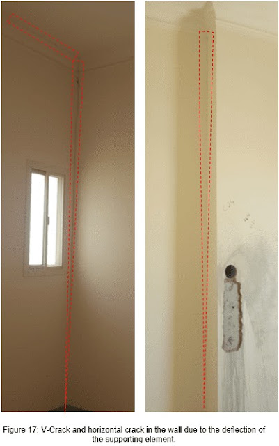
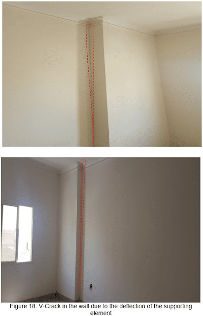
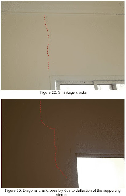
The physical observations made during the inspection are summarized below, and figures from 4 to 26 present part of the visual observation.
1. Various temperature and shrinkage cracks were observed all over the building.
2. Vertical cracks between concrete columns and blockwork were observed in many places.
3. Various Horizontal cracks between the slab and the tiling finish layer were noticed.
4. Cracks near openings were observed in several places.
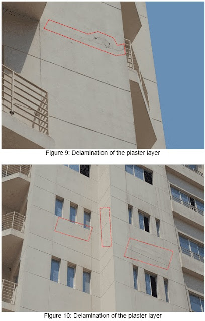
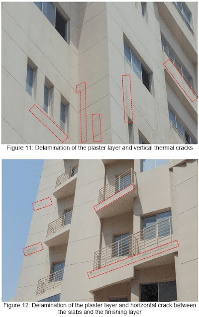
5. Delamination of the plaster layer was noticed in several places in the external finish of the building.
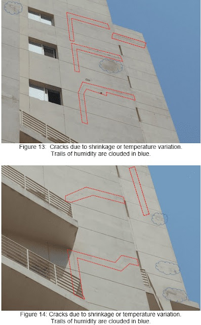
6. Trails of humidity were seen in several spots at the external finish of the building.

- Conducted Tests
Tests, mainly and mostly, were conducted on the columns since they are the critical structural element in the building. The following tests were conducted:
1. Carry out ultrasonic Pulse velocity test as per EN 12504-4:2004.
2. Obtain concrete cores from different locations of the building to assess the physical and mechanical properties of the existing concrete, according to EN 12504-1:2009.
3. Measure the carbonation depth of concrete elements by using the phenolphthalein indicator according to BS 1881-201:1986 and BS EN 14630.
4. Extract reinforcement steel sample for a tensile test following ASTM A370 or ISO 15630-1.
4. Tests Results
The following shows the results of the tests conducted. Table 1 summarizes the conducted tests' results.
4.1 Ultrasonic Test
The ultrasonic test was conducted on several columns and slabs to examine the quality of the concrete in general. Thirty-three columns and five slabs were tested. The results values were varying between 3300 m/s and 4250 m/s. The average velocity was 3831 m/s, which means that the concrete condition is good.
4.2 Compressive strength Test
Thirty-Eight concrete cores were extracted from the entire building, thirty-three cores from the columns, and five cores from the slabs.
Core compressive strength test results vary between 30 MPa and 69.5 MPa for columns. As for the slabs, the compressive strength was between 30.5 MPa and 32.5 MPa. Table 2 present the compressive strength results by implementing the standard deviation to calculate the average concrete strength. The average compressive strength of the concrete was 39.4 MPa, which was considered reasonable for such types of buildings.
4.3 Carbonation Test
No carbonation was observed in the extracted samples.
4.4 Tensile Test
One specimen was extracted from a column to investigate the yield strength of the reinforcement steel used in the structural elements. The yield strength of the deformed bar was above 500 MPa.

5. Discussion of Tests Results and Site
The conducted tests' results show that the concrete condition is good, and the strength of the concrete is in the range of those normally used for such types of buildings. No spalling or corrosion trails were observed, and no carbonation was observed in all extracted cores.
All cracks noticed during the physical inspection were in the blockwork or between the blockwork and the concrete elements. No cracks due to flexural, shear, torsional, or compression distress were observed in the concrete elements.
All observed cracks can be specified either as slight cracks where the crack's width is between 1mm and 5mm or as negligible cracks where the crack's width is less than 1mm.
Due to the absence of the construction drawings, specifications, and method of construction, it was difficult to conclude a definite reason for the cracks. Most of the cracks could be shrinkage cracks and a result of poor quality of construction. Yet, some cracks could be due to a structural cause.
Shrinkage cracks in a concrete block wall can form different patterns depending on where the wall acts to relieve the stresses, which is typically at the change in material or geometry, and adjacent to corners.
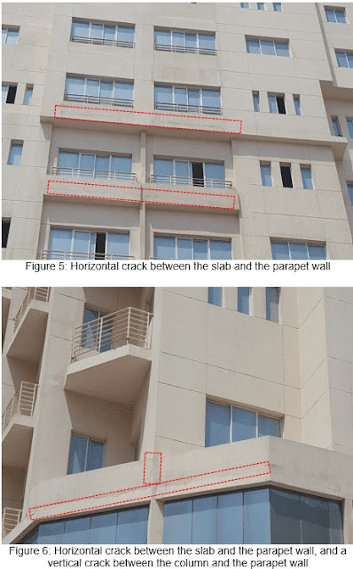
The horizontal crack in figures 4, 5, and 6 is a shrinkage crack between two different materials; the concrete supporting slab and the concrete block parapet. Also, the horizontal crack in figures 7 and 12 is a shrinkage crack between two different materials; the concrete slab and the tiles finishing layer. It is worth mentioning that quality of work and detailing could have a role in developing these cracks, especially noting that these cracks had been occurring in some places.
The vertical cracks of constant crack width are results of shrinkage or thermal expansion. The wall presented in figure 19 has experienced a thermal expansion crack.
The differential strains can occur as a result of different expansion characteristics of two walls or a wall and a column with different Young's Modulus. Furthermore, external walls are subjected to fluctuations of temperature, and hence they tend to deform differently than internal walls, causing cracks in the connecting walls. Figures 8, 9,13, and 14 are examples of such behavior.
Cracks observed at openings and windows are most likely shrinkage cracks, where openings create geometry changes in the wall that serve shrinkage stresses concentrate at the corners. Figures 21 and 22 represent this type of crack.
The vertical cracks with variable crack widths like those shown in figures 16, 17, and 18 have occurred due to structural effects. These cracks could occur due to an excessive deflection of the supporting slab or beam, or the walls had been built before removing the supporting props and allowing the slab to undergo immediate deflection. Also, the diagonal crack that appears at the upper corner of the window in figure 23 could occur due to the deflection in the supporting slab.
The horizontal crack in figure 20 occurred due to the deflection of the supporting element where the bond between the blockwork lack shear strength within the mortar. While the horizontal crack in figure 26 could be a result of either the deflection of the slab above or a shear crack in the bonding mortar due to the wall's thermal expansion.
6. Conclusion
From the preceding observation and test results, the concrete condition is considered good, as the average compressive strength of the core samples tests is 40.9 MPa, and the average result of the ultrasound is 3831 Km/sec (The quality of the concrete could be considered good), as well. It does not show serious defects in the various structural elements except the external and internal cracks between the blockwork and structural elements (columns and slabs) due to the temperature and shrinkage effects on the concrete block walls, and due to the deflection in some supporting elements. Despite that, all cracks could be considered slight or negligible, and some of them are the natural output of temperature variation and shrinkage. Still, the quality of work plays a big role in preventing such cracks from occurring. From the condition of the building, it was obvious to conclude that such quality was absent during the construction process.
The building's structure may need maintenance ranging between 10 to 20 percent due to the existing cracks. However, before conducting any sort of maintenance, it is vital to conduct a thorough inspection and investigation for the root cause of the cracks. It is important to monitor these cracks for some time to understand their nature, static or active cracks.
The above conclusion was based on the observed defects during the inspection period, and tests' results conducted at various selected points that could not reveal the condition of not tested element. Also, to precisely understand the condition and behavior of the building, the construction drawings should be studied in conjunction with observation and tests' results


